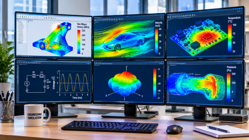
Engineering is not just about understanding equations or learning how physical systems work. It is also about applying that knowledge to solve problems, predict system behaviour, and evaluate whether a design will perform as expected. This is where engineering simulation becomes particularly useful.
Engineering simulation allows students and engineers to develop computational models, apply mathematical principles, and investigate system performance using specialized software. However, completing a simulation project involves much more than opening a software package and running an analysis. It requires a clear understanding of the engineering problem, appropriate model selection, correct parameter configuration, and careful interpretation of results.
For undergraduate students, these projects can be particularly challenging because they combine theoretical knowledge, computational methods, software proficiency, and technical reporting. Understanding the entire simulation process can make these tasks considerably easier to approach.
Understanding Engineering Simulation and Its Applications
Engineering simulation is the process of representing a physical system, component, or process using mathematical models and computational methods. Instead of relying exclusively on physical experiments, engineers can use these models to investigate how a system responds to different operating conditions.
The underlying principles vary depending on the engineering discipline. Structural simulations may use finite element methods to estimate stress and deformation, while electrical simulations may use circuit equations to calculate voltage and current responses.
Simulation is widely used in engineering because it allows designers to investigate different possibilities, identify potential problems, and evaluate design decisions before implementing them physically.
Why Engineering Students Work With Simulation Projects
Simulation assignments are designed to help students connect theoretical engineering concepts with practical applications. A student studying mechanics, for example, may understand the equations governing stress and strain but struggle to visualize how these quantities are distributed throughout a physical component.
A simulation provides a way to investigate these relationships.
Some of the key learning benefits include:
- Applying theoretical knowledge: Students translate mathematical equations and engineering principles into computational models.
- Understanding system behaviour: Simulation results help explain how systems respond to applied forces, electrical inputs, temperature changes, and other operating conditions.
- Evaluating design alternatives: Different configurations can be compared without immediately manufacturing or constructing physical prototypes.
- Developing computational skills: Students gain experience with modelling software, numerical methods, and engineering analysis.
- Improving technical communication: Simulation projects require students to explain their assumptions, methods, results, and conclusions.
The important distinction is that simulation does not automatically guarantee that a design will work in practice. The accuracy of the results depends on the quality of the mathematical model, input parameters, boundary conditions, and assumptions used.
Different Types of Engineering Simulation Projects
Engineering simulation covers several disciplines, each with its own modelling approaches and computational requirements. Understanding these categories helps students identify the appropriate methods and software for their projects.
1. Structural and Mechanical Analysis
Structural simulation investigates how physical components respond to forces, pressure, displacement, and other mechanical loading conditions.
One common application is the analysis of a cantilever beam subjected to an external load. A student can create a model of the beam, define its material properties, apply the appropriate support conditions, and investigate the resulting deformation and stress distribution.
Finite Element Analysis (FEA) is commonly used for these problems. It divides a complex geometry into smaller elements connected at nodes, allowing the governing equations to be solved numerically.
Common structural simulation tasks include:
- Stress and strain analysis.
- Deformation and displacement evaluation.
- Static structural analysis.
- Modal and vibration analysis.
- Fatigue and failure investigations.
- Mechanical component optimization.
Software such as ANSYS Mechanical, Abaqus, SolidWorks Simulation, and Autodesk Fusion can support different types of structural and mechanical analysis.
2. Electrical and Electronic Circuit Simulation
Electrical simulation allows students to investigate circuit behaviour without immediately assembling physical components.
For example, consider a series RLC circuit containing a resistor, inductor, and capacitor. Its response depends on the component values, input signal, and initial conditions.
By constructing a mathematical model or circuit schematic, students can investigate quantities such as current, voltage, resonance frequency, and transient response.
Typical electrical and electronics simulation projects include:
- DC and AC circuit analysis.
- Rectifier and power supply design.
- Operational amplifier circuits.
- Filter design and frequency response.
- Switching converter analysis.
- Digital and analog circuit behaviour.
LTspice, Proteus, Multisim, PSpice, and MATLAB are among the tools used for different circuit simulation and analysis tasks.
3. Power Systems Simulation
Power systems simulation focuses on the generation, transmission, distribution, and utilization of electrical energy.
Unlike simple circuit analysis, power system models can involve interconnected generators, transformers, transmission lines, distribution networks, and electrical loads.
A typical undergraduate project might investigate the voltage profile of a distribution network under varying loading conditions. Another might examine the effects of a fault on system operation.
Common project areas include:
- Load flow analysis.
- Short-circuit and fault analysis.
- Power factor correction.
- Transient stability studies.
- Protection coordination.
- Renewable energy integration.
ETAP, DIgSILENT PowerFactory, PSCAD, and MATLAB/Simulink are examples of software used in power system studies.
4. Electromagnetic and Antenna Simulation
Electromagnetic simulation investigates how electric and magnetic fields interact with materials, conductors, and electromagnetic structures.
It is particularly useful in telecommunications, microwave engineering, electronics, and antenna development.
For example, a student designing a microstrip patch antenna can develop a three-dimensional model, define the substrate properties, configure the excitation, and investigate its electromagnetic performance.
Depending on the project, the analysis may include:
- Antenna radiation patterns.
- Return loss and reflection coefficient.
- Impedance matching.
- Electromagnetic field distribution.
- Resonant frequency.
- Gain and radiation efficiency.
ANSYS HFSS, CST Studio Suite, and COMSOL Multiphysics are commonly used for electromagnetic simulation.
5. Control Systems and Dynamic Modelling
Control systems simulation examines how dynamic systems respond to inputs and how controllers can influence their behaviour.
A typical project might involve modelling a DC motor and designing a controller to regulate its rotational speed.
Students can investigate the system’s transient response, stability, settling time, and response to disturbances.
Common applications include:
- PID controller design.
- Motor speed regulation.
- Robotic system modelling.
- Process control.
- State-space analysis.
- Feedback and feedforward control.
MATLAB, Simulink, and LabVIEW are examples of tools that support different control system modelling and analysis workflows.
6. Thermal and Fluid Flow Simulation
Thermal simulation investigates heat transfer through conduction, convection, and radiation. Fluid flow simulation examines how liquids and gases move under different physical conditions.
These methods are important in applications involving electronic cooling, automotive systems, industrial equipment, and energy systems.
For example, an engineering student investigating electronic component cooling might model heat generation within a component and evaluate temperature distribution under different cooling conditions.
Typical project areas include:
- Heat transfer analysis.
- Temperature distribution.
- Computational Fluid Dynamics (CFD).
- Pressure and velocity distribution.
- Cooling system optimization.
- Thermal management of electronic equipment.
ANSYS Fluent, ANSYS CFX, COMSOL Multiphysics, and OpenFOAM are examples of tools used in these applications.
Popular Engineering Simulation Software and Their Applications
Selecting the right software is an important part of completing an engineering simulation project. Different tools are developed for different modelling requirements, and their capabilities may overlap in certain applications.
Some commonly used engineering simulation platforms include:
| Software | Common Engineering Applications |
|---|---|
| MATLAB | Numerical computation, signal processing, modelling and optimization. |
| Simulink | Dynamic system modelling and control simulation. |
| ANSYS Workbench | Structural, thermal and multiphysics analysis. |
| ANSYS HFSS | Electromagnetic and antenna simulation. |
| COMSOL Multiphysics | Coupled multiphysics modelling. |
| CST Studio Suite | Electromagnetic and RF analysis. |
| LTspice | Analog and switching circuit simulation. |
| Proteus | Circuit and microcontroller simulation. |
| ETAP | Electrical power system analysis. |
| PSCAD | Electromagnetic transient simulation. |
| Abaqus | Advanced structural and nonlinear finite element analysis. |
| SolidWorks Simulation | Mechanical design validation. |
The choice should depend on the engineering problem rather than software popularity.
For instance, MATLAB may be suitable for developing a mathematical model of a control system, while Simulink provides a graphical environment for representing interconnected dynamic components. Similarly, ANSYS Mechanical is suitable for many structural analysis tasks, whereas ANSYS HFSS is designed for three-dimensional electromagnetic simulation.
Students should also consider software availability, licensing requirements, available computational resources, and the specific methods required by their assignment.
A Step-by-Step Approach to Completing an Engineering Simulation Project
A successful simulation project begins long before the first computational analysis is performed. Following a structured workflow helps students avoid unnecessary modelling errors and makes the final results easier to explain.
Step 1: Understand the Engineering Problem
Start by reading the project instructions carefully.
Identify the physical system being investigated, the expected outputs, and the engineering principles involved. Determine whether the project requires structural analysis, circuit simulation, electromagnetic modelling, control system design, or another form of analysis.
For example, a project investigating the deformation of a loaded beam requires a different modelling approach from one examining the frequency response of an electronic filter.
Write down the required parameters, assumptions, and deliverables before selecting the software.
Step 2: Develop the Mathematical Model
The mathematical model describes the behaviour of the physical system.
Depending on the project, this may involve differential equations, algebraic relationships, material constitutive equations, circuit laws, or governing equations for fluid flow.
For a simple series RLC circuit, the relationship between voltage, current, resistance, inductance, and capacitance can be expressed using Kirchhoff’s voltage law.
For a structural problem, the model may involve relationships between applied forces, material properties, stress, and deformation.
Understanding these relationships is important because simulation software solves a mathematical representation of the system, not the physical system directly.
Step 3: Select the Appropriate Simulation Software
Once the problem and mathematical model are understood, select a suitable software package.
Consider the type of analysis required, the complexity of the geometry, the numerical methods involved, and the expected outputs.
A circuit analysis project might use LTspice, while a structural mechanics project could use ANSYS Mechanical or Abaqus.
Avoid selecting software simply because it is widely used. The best tool is the one that supports the modelling requirements of the particular project.
Step 4: Configure the Simulation Model
This stage involves translating the mathematical description into a computational representation.
Depending on the software, it may involve:
- Creating or importing geometry.
- Defining materials and their properties.
- Assigning electrical or mechanical components.
- Setting boundary conditions and initial conditions.
- Defining input signals and excitation sources.
- Generating a computational mesh where required.
- Configuring solver settings and simulation time.
Errors introduced during model configuration can significantly affect the final results.
For example, assigning an incorrect material property to a structural component can produce misleading stress and deformation predictions.
Step 5: Run the Simulation and Examine Convergence
After configuring the model, execute the appropriate solver.
However, obtaining a completed simulation does not automatically mean the results are accurate.
Students should examine solver warnings, convergence behaviour, numerical stability, and whether the selected settings are appropriate for the problem.
In finite element analysis, mesh refinement studies can help establish whether important results are sensitive to mesh size. In circuit simulation, time-step selection and solver settings can influence how transient behaviour is represented.
Step 6: Interpret the Results
Simulation results need engineering interpretation.
A structural analysis may produce stress contours, displacement plots, and deformation profiles. An electrical simulation may produce voltage and current waveforms, frequency response plots, or power measurements.
Students should identify the important trends and compare the results against theoretical expectations or appropriate reference values.
For example, if a beam experiences increasing deformation as the applied load increases, the relationship should be consistent with the underlying structural model and its assumptions.
Avoid presenting screenshots without explaining what they demonstrate.
Step 7: Validate the Model and Document the Findings
Validation is an important part of engineering simulation.
Where possible, compare the results with analytical calculations, experimental measurements, published reference data, or an independent computational method.
Document the assumptions, material properties, input parameters, solver settings, and relevant limitations.
A good technical report should explain:
- The engineering problem and project objectives.
- The theoretical background.
- The modelling methodology.
- The software and simulation settings.
- The results and their interpretation.
- Validation and limitations.
- Conclusions and recommendations.
This makes the project easier to review, reproduce, and understand.
Common Mistakes in Engineering Simulation Projects
Even when students understand the underlying engineering concepts, certain modelling and analysis mistakes can compromise their projects.
Using Incorrect Material Properties
Material properties directly influence simulation results. Incorrect values for Young’s modulus, density, thermal conductivity, or electrical conductivity can lead to misleading predictions.
Always verify material data using appropriate technical references and ensure that the selected material model matches the assumptions of the analysis.
Applying Unrealistic Boundary Conditions
Boundary conditions describe how a system interacts with its surroundings.
For example, incorrectly constraining a structural component can produce unrealistic deformation or stress distributions. Similarly, an incorrectly configured electrical reference or excitation source can affect circuit behaviour.
Students should ensure that the simulation represents the intended physical conditions.
Ignoring Mesh Quality and Convergence
In finite element and computational fluid dynamics projects, mesh quality influences numerical accuracy.
A coarse mesh may fail to capture important variations in stress, temperature, or velocity. However, increasing the number of elements indefinitely is not always practical.
Mesh refinement and convergence assessment help establish whether the results are sufficiently stable for the intended analysis.
Treating Simulation Results as Automatically Correct
A software package can successfully complete a calculation while the underlying model remains incorrect.
Students should question unexpected results, examine solver warnings, check units, and compare outputs with theoretical expectations.
Simulation should support engineering reasoning, not replace it.
Presenting Results Without Technical Explanations
A report containing only screenshots, graphs, and numerical values does not demonstrate a complete understanding of the engineering problem.
Every important result should be accompanied by an explanation of what it represents, why it occurs, and how it relates to the project objectives.
How to Present and Document Engineering Simulation Results
Technical documentation is an essential part of engineering simulation projects.
A well-organized report allows another person to understand how the model was developed, which assumptions were made, and how the conclusions were reached.
Start with a clear description of the problem and its objectives. Introduce the governing engineering principles before explaining the modelling methodology.
Include relevant diagrams, circuit schematics, geometry illustrations, mesh representations, and simulation plots.
When presenting numerical results, provide units and identify the conditions under which the results were obtained.
Graphs should have clearly labelled axes, appropriate scales, and captions that explain their purpose. If multiple configurations are compared, present the results in a consistent format.
Most importantly, distinguish between simulation predictions and experimentally verified performance. This demonstrates a proper understanding of the limitations of computational modelling.
Using Engineering Simulation Support Responsibly
Engineering simulation assignments can involve several interconnected challenges, from developing mathematical models to configuring software and interpreting computational results.
Students who encounter difficulties should seek guidance early rather than waiting until the project deadline approaches.
Academic support is most useful when it helps students understand the engineering principles behind their work. This may involve explanations of numerical methods, guidance on software functionality, feedback on modelling assumptions, or assistance interpreting simulation outputs.
Before using external academic support, students should check their institution’s academic integrity requirements and ensure that any assistance received is permitted.
A responsible approach should strengthen a student’s ability to develop, explain, and evaluate engineering models independently.
Start Your Engineering Simulation Project With the Right Guidance
If you are finding it difficult to understand a simulation method, configure an engineering model, or interpret your results, getting guidance at the right stage can make the learning process easier.
Quality Assignment Help connects students with subject experts who can provide guidance across different engineering disciplines and technical subjects.
Get a free quote for your engineering assignment and explore the available academic support for your project.